PV Wire on Trackers and Moving Arrays
A tracker does not damage a pv wire with one big force; it damages it with thousands of small ones. KUKA CABLE publishes an outer diameter of 5.5 mm at 4 mm², 6.0 mm at 6 mm² and 7.5 mm at 10 mm² for its solar range, together with a minimum bending radius of 4 × the outer diameter — which is the figure that decides whether a cable survives the moving side of a single-axis array.

Key takeaways
- Published diameters are 5.5 mm, 6.0 mm and 7.5 mm for 4 mm², 6 mm² and 10 mm², so the bending limit follows the size.
- The minimum bending radius is published as 4 × the outer diameter, giving 22 mm, 24 mm and 30 mm on those three sizes in my own arithmetic.
- Static flexibility, cold bending, cold elongation and abrasion tests all appear on the manufacturer's published test list.
- The site publishes no cable-carrier or loop-length recommendation, so the mechanical design of a moving run stays with the installer.
What a tracker actually does to a cable
Single-axis trackers rotate to follow the sun, which means every cable crossing from a fixed structure to a moving one is bent, straightened and re-bent on a daily cycle. The amplitude is small and the count is enormous. A cable that is bent to a fixed radius once and left alone behaves quite differently from one pulled repeatedly to the same radius at dawn and dusk.
The published construction helps here. The conductor is tinned copper with class 5 flexibility to IEC 60228 — 56 strands of 0.29 mm at 4 mm², 84 at 6 mm², 142 at 10 mm². Fine stranding spreads a bending strain across many wires instead of concentrating it in a few, which is why a flexible class is specified for a moving application rather than a solid conductor.
The jacket contributes the rest. Insulation and sheath are both XLPO, electron-beam cross-linked and LSHF, with 0.7 mm of insulation and 0.8 mm of sheath on the smaller sizes. A cross-linked layer resists the creep that a thermoplastic jacket suffers after repeated flexing in warm conditions.
Radius, not slack, is the first decision
The published limit is 4 × the outer diameter. Applied to the three commonly used sizes, that gives 22 mm at 4 mm², 24 mm at 6 mm² and 30 mm at 10 mm². This is my own multiplication of the published diameters, and it assumes a single clean bend on a cable at normal ambient temperature. A service loop that is pulled tight enough to sit inside a smaller radius is working against the design, not with it.
Loops are where the arithmetic gets practical. A tracker arm that moves through a wide arc needs enough cable between the fixed combiner and the moving rail to absorb the whole sweep without tension, and the loop has to hold its shape over both extremes of travel. Too little slack puts the terminations in tension; too much leaves a loop that can catch on a purlin or abrade against the rail as the array moves.
Bending cycles, counted
Work out the travel involved before choosing a loop. Take a run with a one-metre arm from the pivot to the cable crossing, moving 60 degrees either side of centre. The tip travels an arc of 2 × (60/360) × 2 × π × 1 m, which is 2.09 m per full movement. That figure is mine, and it assumes a rigid arm, a cable crossing at the arm tip and no lost motion in the bearings.
Then multiply by time. Two full movements a day for 20 years is 14,600 cycles; at 2.09 m each, the cable at that crossing accumulates roughly 30.5 km of travel. Again my arithmetic, and it assumes continuous operation with no downtime. A fixed-tilt array accumulates none of it. That is the number to hold in mind when a loop is designed to the minimum rather than with a spare centimetre.
What the published tests cover
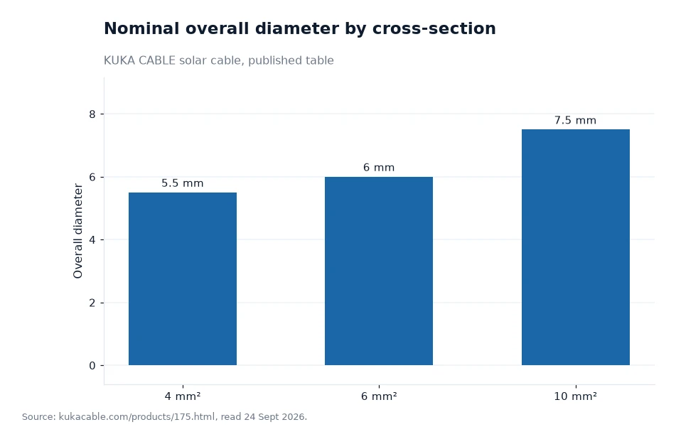
The bars show why the mechanical question cannot be answered from the cross-section alone. Moving from 4 mm² to 10 mm² raises the conductor area by a factor of 2.5, while the outer diameter grows by only 36%, from 5.5 mm to 7.5 mm. My arithmetic on the published diameters. The bending radius follows the diameter, so it rises by the same 36%, but the mass per metre rises by 120%, from 59 g/m to 130 g/m.
That combination is what makes a heavier cable harder on a moving run: a bigger radius is needed, and more mass is being carried through every cycle. Support points, cable carriers and strain relief all have to be sized for the weight rather than for the diameter, so the two numbers to pull off a pv wire datasheet are the measured outer diameter and the nominal weight per metre.
Tests that answer the movement question
The manufacturer's published test list is the place to look, because four entries speak directly to a moving array. Static flexibility testing covers how the cable behaves when repeatedly bent. Cable abrasion testing covers the wear that a loop experiences against a rail or a guide. Cold bending and cold elongation cover the winter case, when the jacket is stiffest and the tracker still moves at dawn. None of those tests is a tracker-cycle qualification, and the site does not claim one.
Two further published figures support the same mechanical story. Tensile strength before ageing is given as at least 8 N/mm², which is the force the insulation must withstand before it tears, and elongation before ageing as at least 125%, with the site stating that its PV cables typically reach about 20% higher, up to 185%. The range is described against TUV 2PfG 1169/08.2007, EN 50618:2014 and IEC 62930. A jacket with more stretch available absorbs more of the daily movement before it cracks.
| Cross-section | Overall diameter | Nominal weight | Bending radius at 4 × diameter (my arithmetic) |
|---|---|---|---|
| 1.5 mm² | 4.6 mm | 34 g/m | 18.4 mm |
| 2.5 mm² | 5.0 mm | 45 g/m | 20.0 mm |
| 4 mm² | 5.5 mm | 59 g/m | 22.0 mm |
| 6 mm² | 6.0 mm | 78 g/m | 24.0 mm |
| 10 mm² | 7.5 mm | 130 g/m | 30.0 mm |
| 16 mm² | 8.8 mm | 190 g/m | 35.2 mm |
Worked example
Size a service loop from published figures rather than from habit. Take a 6 mm² run at 78 g/m crossing from a fixed combiner to a moving rail, with a two-metre loop. The cable mass in that loop is 78 g/m × 2 m, or 156 g, which is light enough that the loop will not sag under its own weight; the same loop in 10 mm² at 130 g/m carries 260 g, and in 16 mm² at 190 g/m it carries 380 g. Each of those multiplications is mine, from the published nominal weights.
Now compare those masses with the bending limits. The 6 mm² loop must never be pulled inside a 24 mm radius, and the 10 mm² loop never inside 30 mm. A loop that is 400 mm long but drawn tight around a 20 mm guide is out of specification on the first movement, whatever its total length. The published figures give the limits; the loop geometry has to respect them.
Frequently asked questions
Is there a published cycle life for a tracker application?
No. The manufacturer publishes a test list that includes static flexibility, abrasion, cold bending and cold elongation, plus tensile strength of at least 8 N/mm² and elongation of at least 125% before ageing, but it publishes no tracker-cycle rating and no minimum loop length, so those remain installation design decisions.
Which cross-section suits a moving run?
The site names 4 mm², 6 mm² and 10 mm² as the commonly used specifications, with published outer diameters of 5.5 mm, 6.0 mm and 7.5 mm. Since the bending radius follows the diameter, the smallest size that satisfies the voltage drop requirement usually gives the easiest mechanical design.
What to specify before the trackers arrive
Write the loop length, the guide radius and the strain relief into the installation drawing, using the published radius of four times the outer diameter as the hard limit at every guide. Check the winter case as well: the ambient range is published as −40 °C to +90 °C, and the cold bending and cold elongation tests exist because a stiff jacket at dawn is the least forgiving moment in a tracker cycle.
Then ask for the documents that make the mechanical plan checkable: the datasheet with the measured diameter, the test record for the batch, and the certificate copy naming the standard. The manufacturer publishes these across its own pages, including the solar cable section, the cross-section table and a topic section on construction and on the consequences of cutting corners.
Dimensions and weights for tracker arrays come from the manufacturer's site; the diameter table for 4, 6 and 10 mm² was listed 24 Sept 2026[1].